CN
-
Service Hotline
15766086363


Release Date:Mar 05, 2026
Reverse PCB Documentation is the systematic process of creating comprehensive, technical records of a bare Printed Circuit Board (PCB) by extracting design details—including layer stackups, trace routing, component footprints, material specifications, and manufacturing parameters—from a physical board. Unlike standard PCB documentation (created during original design), this process reconstructs records when original files are lost or unavailable, making it essential for legacy PCB maintenance, replication, or modification.
The workflow starts with Physical & Structural Documentation: The PCB’s dimensions (length, width, thickness) are measured using calipers and 3D scanners. Mounting hole positions, sizes, and tolerances are recorded, along with edge cuts or notches. Layer count is determined via X-ray tomography (non-destructive) or chemical etching (destructive), and each layer’s thickness and dielectric material (e.g., FR-4, prepreg) are documented to create a layer stackup diagram.
Next is Electrical & Layout Documentation: High-resolution images of each layer are captured and aligned to create a detailed trace routing map—recording trace widths, spacing, and net names (e.g., “VCC_3.3V”, “UART_RX”). Component footprints are documented with pad dimensions, spacing, and reference designators (e.g., “R1”, “U2”), cross-referenced with IPC standards to ensure clarity. Via specifications (type: through-hole/blind/buried; diameter; plating thickness) are recorded using X-ray imaging and micrometers.
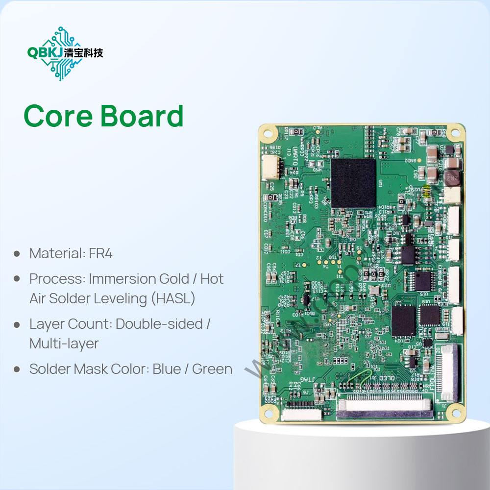
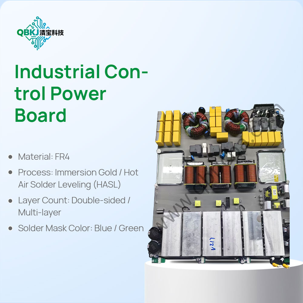
Then comes Material & Manufacturing Documentation: The PCB’s substrate material, copper thickness (e.g., 1oz, 2oz), and surface finish (e.g., ENIG, HASL) are identified via material testing (e.g., Fourier-transform infrared spectroscopy for substrate analysis) and visual inspection. Manufacturing parameters like solder mask color, silkscreen ink type, and thermal relief designs are documented to ensure replication matches the original.
Finally, Document Compilation: All data is organized into standard formats—Gerber files for manufacturing, drill files for holes, layer stackup reports, and a bill of footprints (BOF). These documents are validated by comparing them to the physical PCB via overlay analysis and DFM checks. Challenges include documenting high-density PCBs with fine-pitch traces and reconstructing obsolete manufacturing parameters. This process is critical for ensuring consistent PCB replication, facilitating repairs, and complying with quality management systems (e.g., ISO 9001).
Email: 1330695973@qq.com
Factory: Room 703, Kelunte R&D Building, No. 1 Ganli 5th Road, Jihua Street, Longgang District, Shenzhen City