CN
-
Service Hotline
15766086363


Release Date:Mar 02, 2026
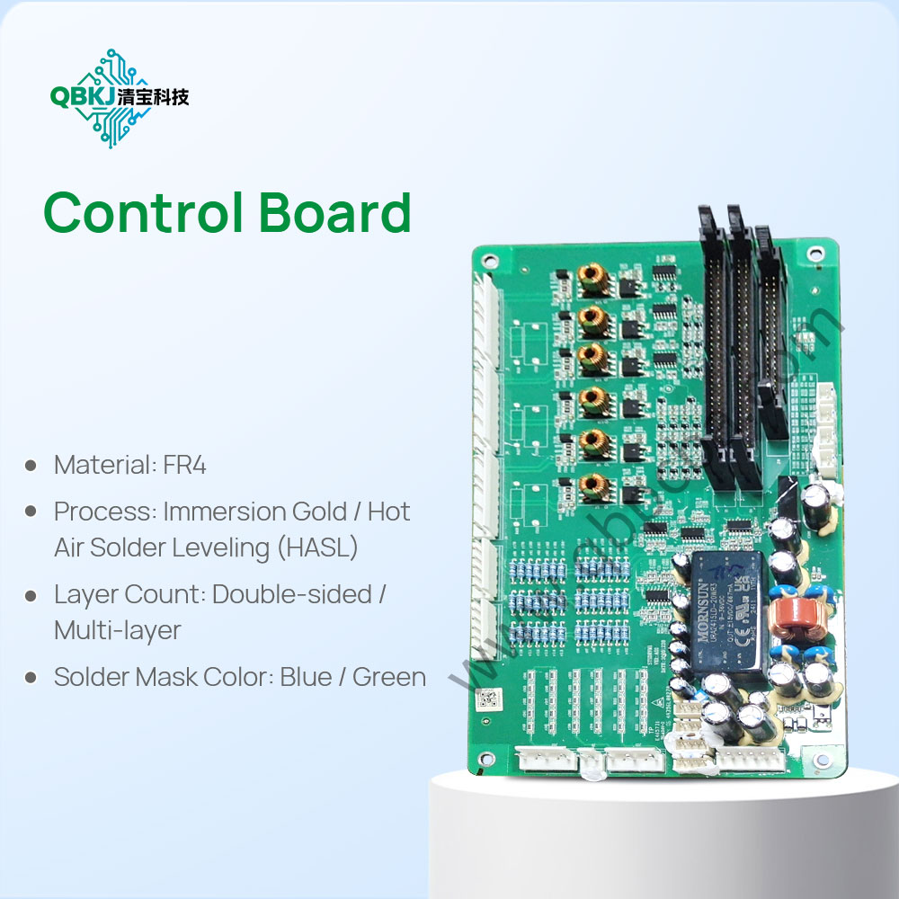
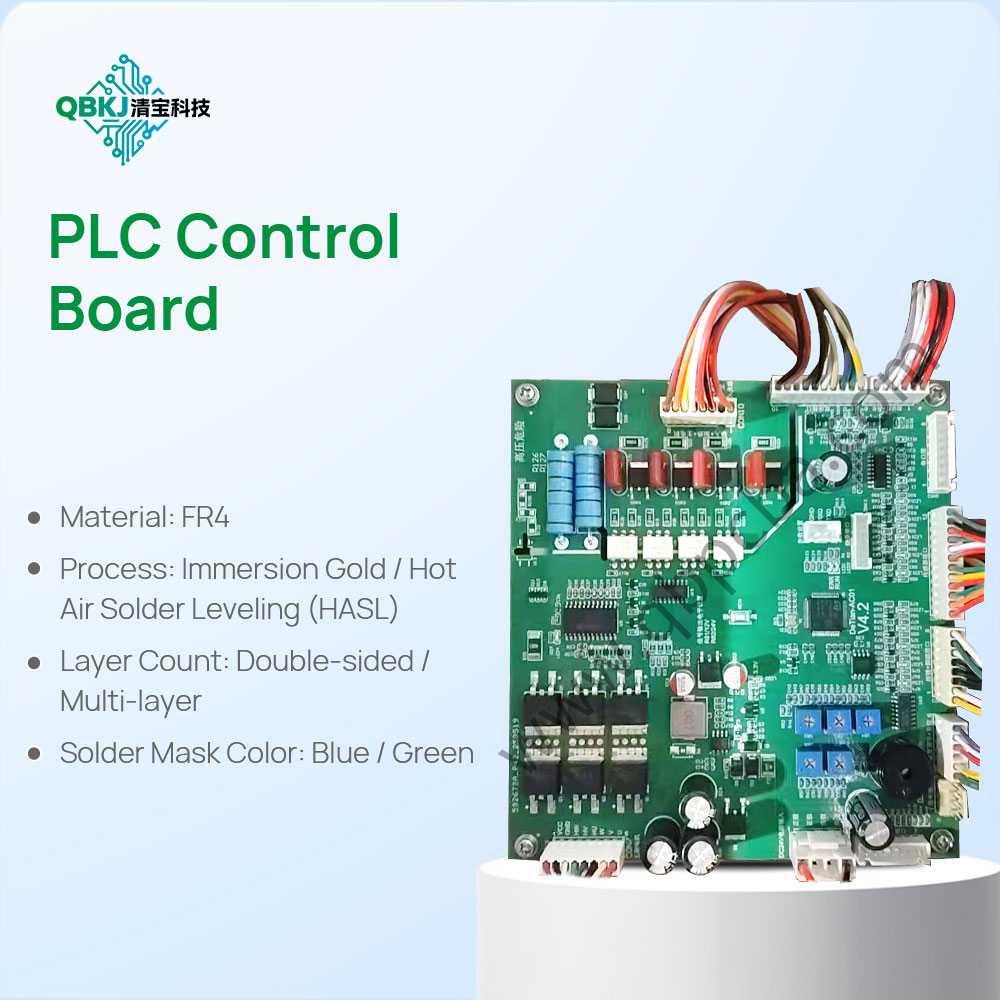
PCB Board Reverse Engineering is the process of extracting complete design data from a physical bare PCB (Printed Circuit Board)—including trace routing, layer stackups, via types (through-hole, blind, buried), component footprints, and material specifications—without access to original design files. Unlike PCBA reverse engineering (which includes component analysis), this focus solely on the bare board’s structure, making it essential for replicating legacy boards, modifying designs for custom applications, or verifying compliance with industry standards.
The process begins with Preparatory Documentation: Technicians capture high-resolution images of the PCB’s top and bottom layers using specialized cameras or 3D scanners to create a digital reference. They also note physical dimensions, mounting holes, and any labeling (e.g., part numbers, revision codes) to ensure accuracy.
Next is Layer Stackup Analysis: For multi-layer PCBs, experts use techniques like chemical etching (removing outer layers one by one to expose inner traces) or X-ray tomography (visualizing layers non-destructively) to determine the number of layers, dielectric material type (e.g., FR-4, Rogers), and layer thicknesses. This step is critical for ensuring signal integrity and thermal performance in replicated boards.
Then, Trace and Via Mapping: Using circuit tracers or multimeters, technicians map the path of every trace, noting width, spacing, and connections to pads or vias. For blind or buried vias (which do not pass through all layers), X-ray imaging is used to confirm their depth and connections to inner layers. Component footprints are documented, including pad size, shape, and spacing, to ensure compatibility with original or replacement components.
Finally, Design File Generation: The mapped data is converted into industry-standard design files—including Gerber files (for PCB fabrication), drill files (for via and mounting hole drilling), and schematic PDFs (for reference). These files are validated via electrical testing (e.g., continuity checks to ensure no open or short circuits) and cross-referenced with industry standards (e.g., IPC-2221 for trace width requirements). Key challenges include decoding complex trace patterns in high-density PCBs and matching the original board’s material properties (e.g., thermal conductivity, dielectric constant), which require advanced tools and material testing. This process is indispensable for businesses needing to replace obsolete PCBs, customize boards for specific applications, or conduct failure analysis on bare boards.
Email: 1330695973@qq.com
Factory: Room 703, Kelunte R&D Building, No. 1 Ganli 5th Road, Jihua Street, Longgang District, Shenzhen City