CN
-
Service Hotline
15766086363


Release Date:Jan 26, 2026
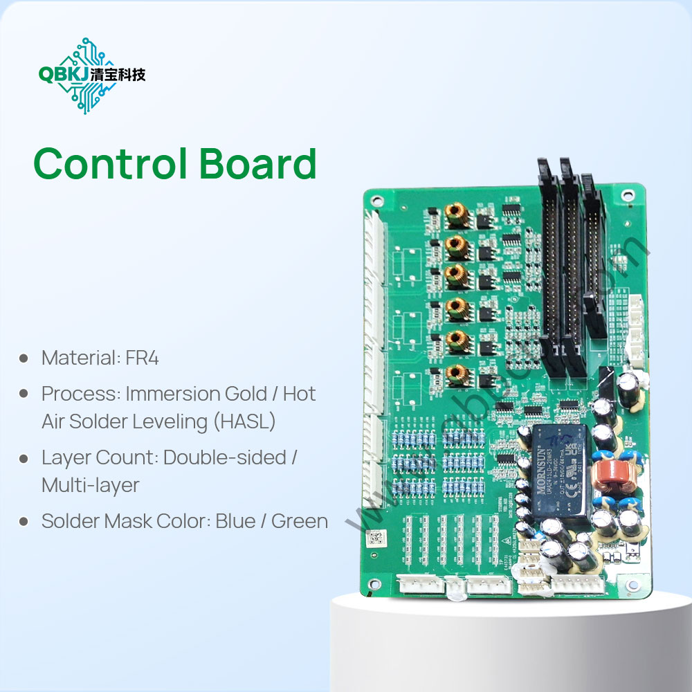
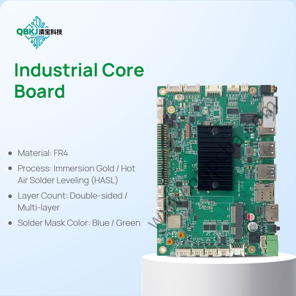
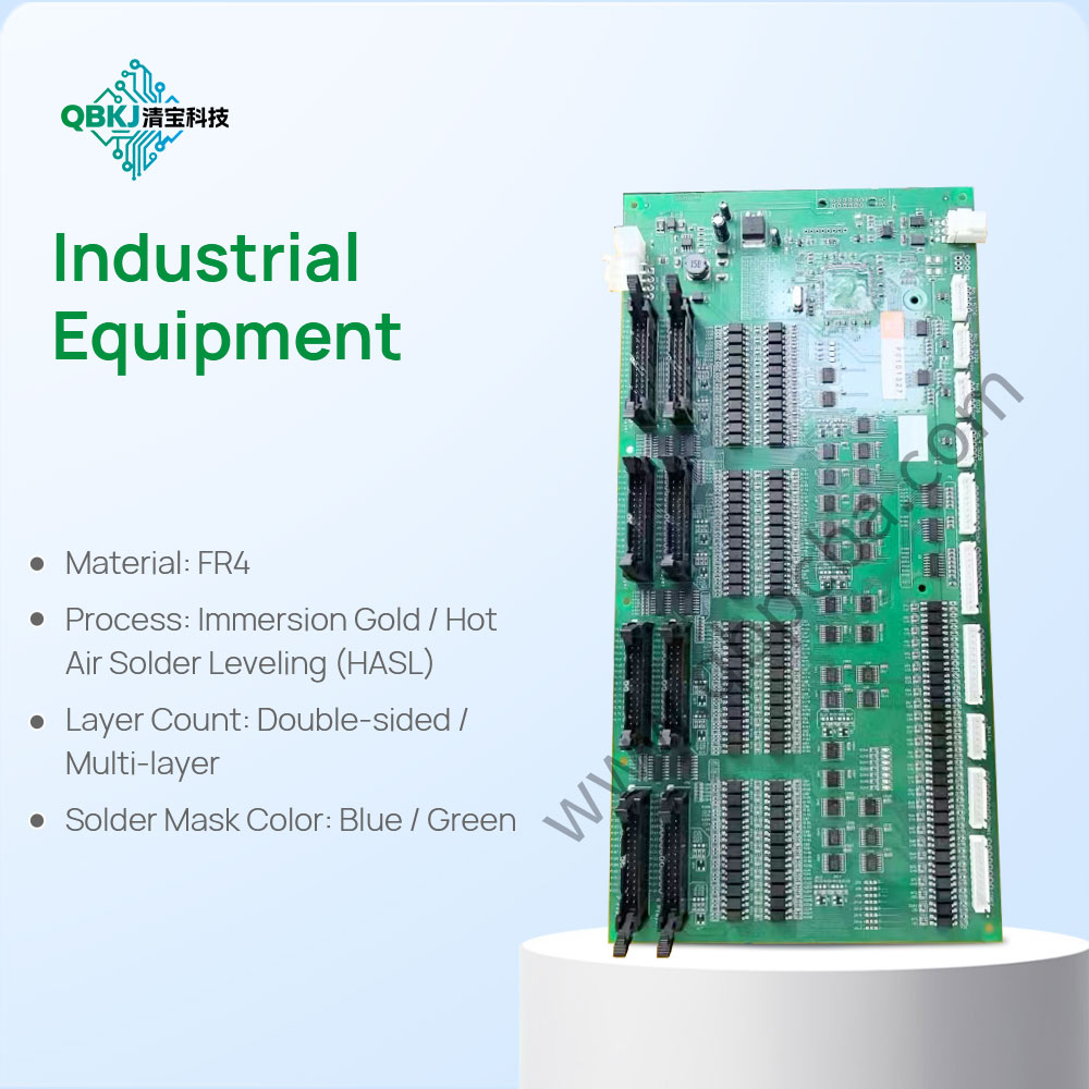
PCBA reverse analysis combines PCB reverse engineering with component-level investigation to fully replicate or modify an assembled printed circuit board assembly. Unlike standalone PCB analysis (which focuses on the bare board) or basic teardown (which only documents components), PCBA reverse analysis delves into both the board’s physical structure and the functional interactions between its components. The process starts with documenting the entire assembly: technicians log each component’s part number, manufacturer, and orientation (using magnifiers or microscopes for small parts like SMD chips) before carefully desoldering components to avoid damage.
After disassembly, PCB reverse analysis proceeds (as outlined earlier) to map traces and create schematics, while component analysis involves verifying each part’s specifications (e.g., a capacitor’s capacitance/voltage rating or a microcontroller’s pinout) via datasheets or electrical testing (e.g., using an oscilloscope to measure signal output). Once both the PCB design and component data are compiled, technicians rebuild the PCBA in simulation software (e.g., Altium Designer or Proteus) to test functionality—ensuring that the reversed design matches the original’s performance (e.g., power consumption, signal integrity). This process is invaluable for repairing obsolete equipment (e.g., industrial controllers with no replacement parts), customizing off-the-shelf PCBs (e.g., adding wireless modules), or conducting IP audits (checking for patent infringement). However, it demands extensive knowledge of both hardware and software (especially for programmable components like FPGAs) and ethical compliance (avoiding unauthorized replication of copyrighted designs).
Email: 1330695973@qq.com
Factory: Room 703, Kelunte R&D Building, No. 1 Ganli 5th Road, Jihua Street, Longgang District, Shenzhen City