CN
-
Service Hotline
15766086363


Release Date:Mar 13, 2026
PCBA Prototype Clone Manufacturing is the process of creating small-batch (typically 1–20 units) functional replicas of a target PCBA for testing, validation, or design iteration—integrating precise PCB cloning, component sourcing, and manual/automated assembly to balance accuracy with rapid turnaround. Unlike mass-produced PCBA clones (optimized for volume), this process prioritizes flexibility, allowing for quick adjustments (e.g., component substitutions, design tweaks) to validate form, fit, and function before scaling. It is critical for R&D teams, startups, or legacy equipment maintenance where small quantities of validated PCBAs are needed to test performance, compatibility, or repair solutions.
The process begins with Original PCBA Forensics: Technicians use 3D optical scanners (±10μm accuracy) to capture component positions (X/Y/Z coordinates) and orientations (e.g., IC pin 1 alignment, diode polarity). High-resolution X-ray imaging documents BGA solder ball geometry and inner-layer trace connections, while a digital multimeter records component values (resistor ohms, capacitor capacitance) for the BOM. A “golden sample” of the original PCBA is retained for side-by-side testing.
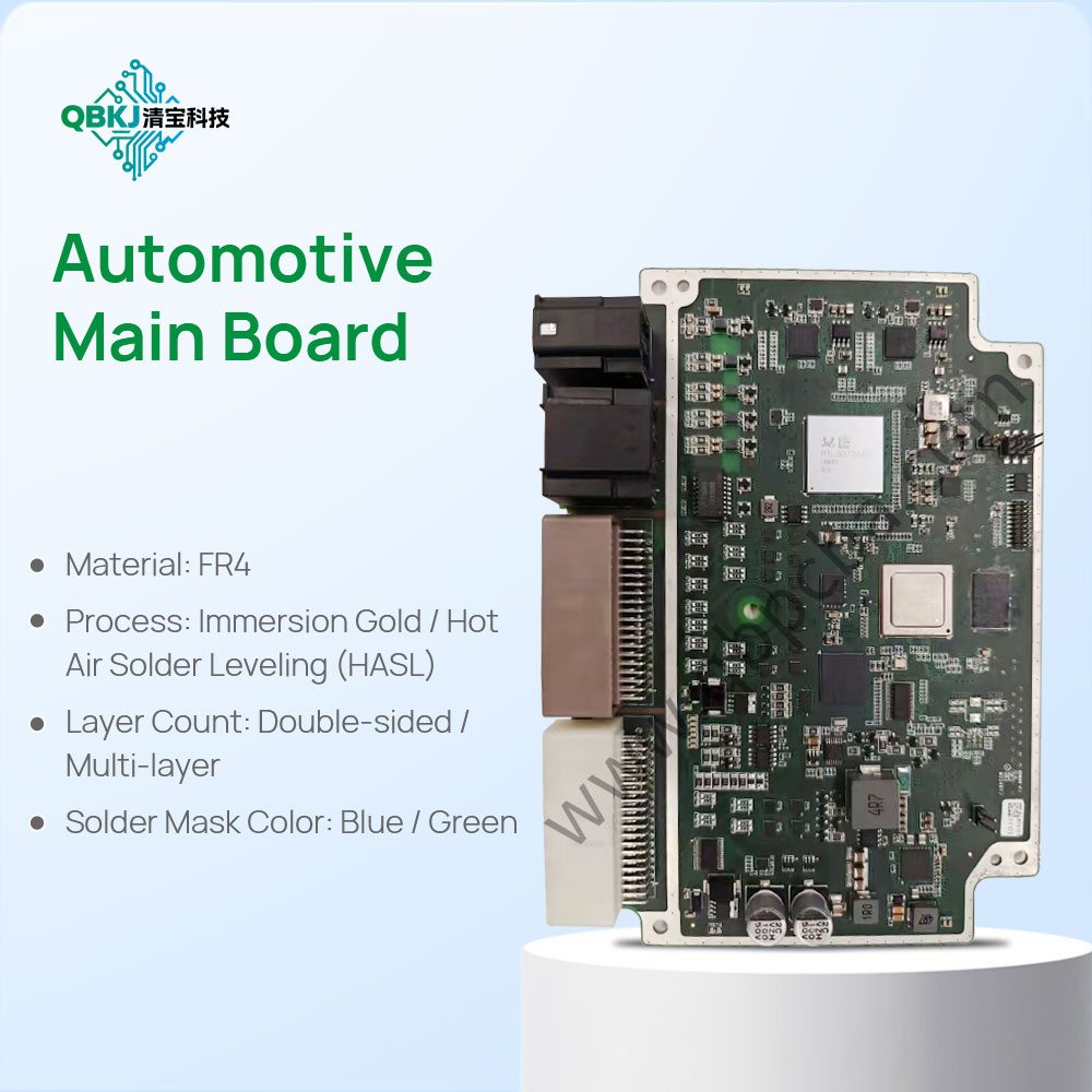
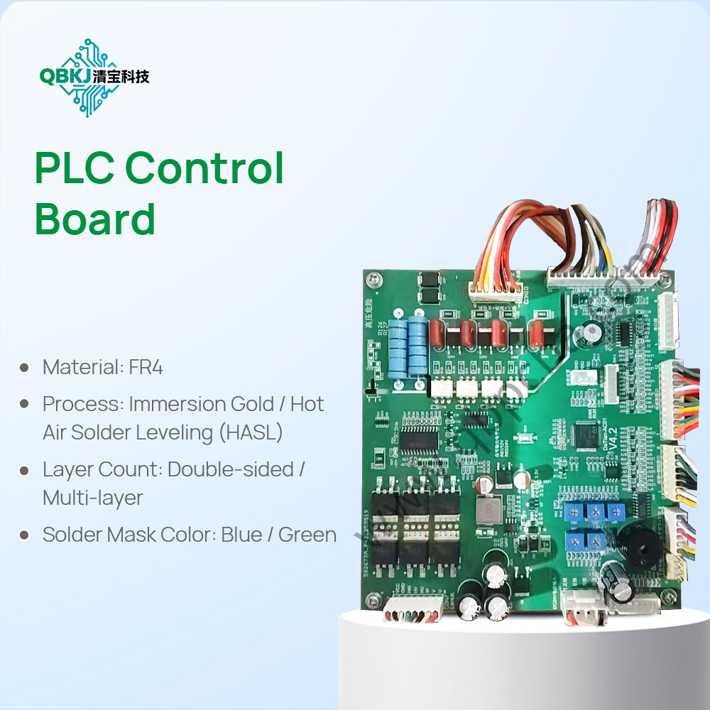
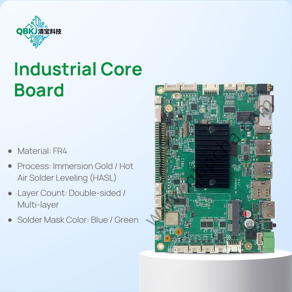
Next is PCB Prototype Clone Fabrication: The original PCB’s design is reverse-engineered to generate Gerber files, which are used to fabricate small-batch bare PCBs. Materials are matched to the original (e.g., FR-4 substrate, 1oz copper, ENIG surface finish) but may use prototype-grade alternatives for faster delivery. These PCBs are tested for continuity (no open/short circuits) and impedance (matching high-speed signal requirements) to ensure electrical alignment with the original.
Component sourcing follows Practicality & Accuracy: Exact components are sourced from authorized distributors where possible; obsolete parts are replaced with equivalents matching form (package size), fit (footprint), and function (electrical specs). Components are tested individually (e.g., oscilloscopes for microcontrollers, LCR meters for passives) to confirm performance—e.g., a sensor’s output range is verified to match the original.
Assembly combines Automation & Manual Precision: SMT components are placed via benchtop pick-and-place machines (calibrated to 3D-scanned coordinates) for accuracy, while through-hole components are soldered manually. Solder paste type and reflow profiles are matched to the original to ensure solder joint integrity, with visual inspection via a digital microscope to check for cold joints or bridging.
Finally, Validation Testing: Cloned prototypes undergo functional testing (applying input signals to confirm output matching the golden sample), in-circuit testing (ICT) to verify component connections, and environmental stress testing (e.g., temperature cycling from -20°C to 60°C) to assess reliability. Adjustments—such as replacing a faulty component or resizing a trace—are made quickly, with new prototypes fabricated in 3–7 days. Challenges include sourcing rare components (via specialty distributors) and balancing speed with accuracy (e.g., manual soldering variations). This process delivers validated PCBA prototypes to accelerate testing and design iteration.
Email: 1330695973@qq.com
Factory: Room 703, Kelunte R&D Building, No. 1 Ganli 5th Road, Jihua Street, Longgang District, Shenzhen City