CN
-
Service Hotline
15766086363


Release Date:Mar 13, 2026
PCB Prototype Copy Manufacturing is the process of producing small-batch (typically 1–50 units) bare PCB prototypes using design data extracted from an existing reference PCB (original or copy)—focused on speed, flexibility, and accuracy to validate design changes, test form-fit, or prepare for mass production. Unlike mass production (optimized for volume), this process prioritizes rapid turnaround and adaptability, making it ideal for R&D teams, startups, or legacy equipment maintenance where small quantities of custom or hard-to-source PCBs are needed.
The process begins with Reference PCB Analysis: The reference PCB (e.g., a legacy board or a competitor’s design) is reverse-engineered to capture critical details—layer stackup (via X-ray or manual peeling for small batches), trace routing (documented via high-resolution imaging), and via specifications (drill size, plating type). Design files (Gerber, drill) are generated using PCB software (e.g., KiCad, Altium) with a focus on retaining the reference’s critical dimensions (e.g., mounting hole positions, component footprints) while allowing minor adjustments (e.g., adding test points for prototype testing).
Next is Prototype Design Validation: The reversed design files are reviewed for DFM (Design for Manufacturing) suitability for small-batch production—e.g., ensuring trace widths are ≥0.1mm (for easy etching) and vias are ≥0.3mm (for manual drilling if needed). A 3D render of the PCB is created to verify form-fit with enclosures or adjacent components, and a single “test unit” is often fabricated first to confirm alignment with the reference.
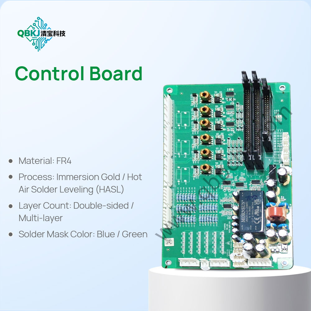
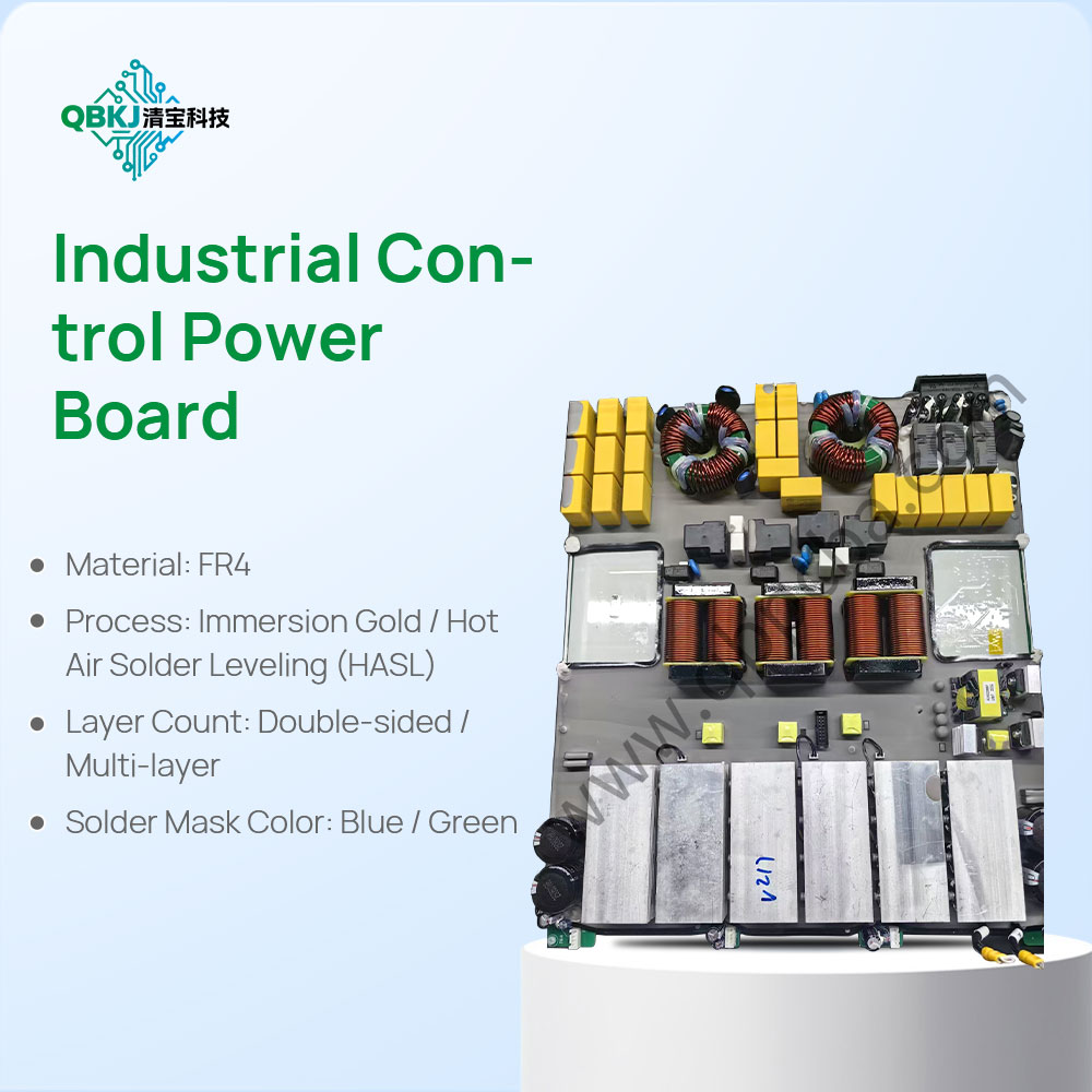
Material sourcing is flexible: Prototype-Grade Materials: Substrates (e.g., FR-4 for standard prototypes, flexible polyimide for wearable designs) and copper thickness (1oz for most prototypes) are selected to match the reference’s performance requirements without the cost of bulk ordering. Surface finishes (e.g., OSP for quick turnaround, ENIG for prototypes requiring soldering tests) are chosen based on testing needs.
Manufacturing is optimized for speed: Small-Batch Fabrication: PCBs are fabricated using rapid prototyping techniques—laser cutting for substrate shaping, inkjet printing for trace patterns (replacing photomasks for faster setup), and chemical etching (manual or semi-automated) for copper removal. Vias are drilled via CNC machines (with quick-change tooling) and plated using electroless copper deposition (for small batches). For ultra-fast turnaround (24–48 hours), some manufacturers offer “express” services with streamlined steps.
Quality control is targeted: Prototype-Specific Testing: Each prototype PCB is inspected for visual defects (e.g., trace peeling, uneven solder mask) using a digital microscope. Electrical testing includes continuity checks (to ensure no open circuits) and impedance testing (for high-speed prototypes). A sample prototype is assembled with dummy components to verify footprint compatibility and form-fit with enclosures—critical for validating the design before scaling.
Finally, Iteration Support: If adjustments are needed (e.g., resizing a mounting hole, adding a trace), the design files are modified quickly, and new prototypes are fabricated in days. This iterative process allows teams to test multiple versions of the PCB copy without long lead times. Challenges include balancing speed with accuracy (e.g., manual etching leading to minor trace variations) and sourcing specialty materials (e.g., high-temperature substrates) for niche prototypes. This process delivers fast, flexible PCB prototype copies to accelerate testing and development.
Email: 1330695973@qq.com
Factory: Room 703, Kelunte R&D Building, No. 1 Ganli 5th Road, Jihua Street, Longgang District, Shenzhen City