CN
-
Service Hotline
15766086363


Release Date:Mar 12, 2026
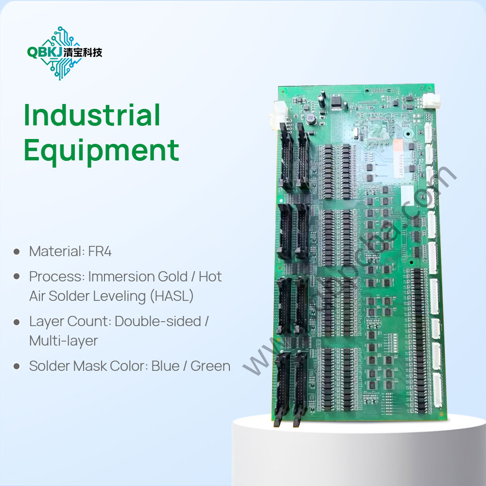
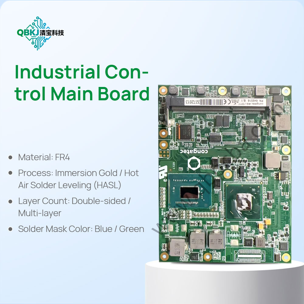
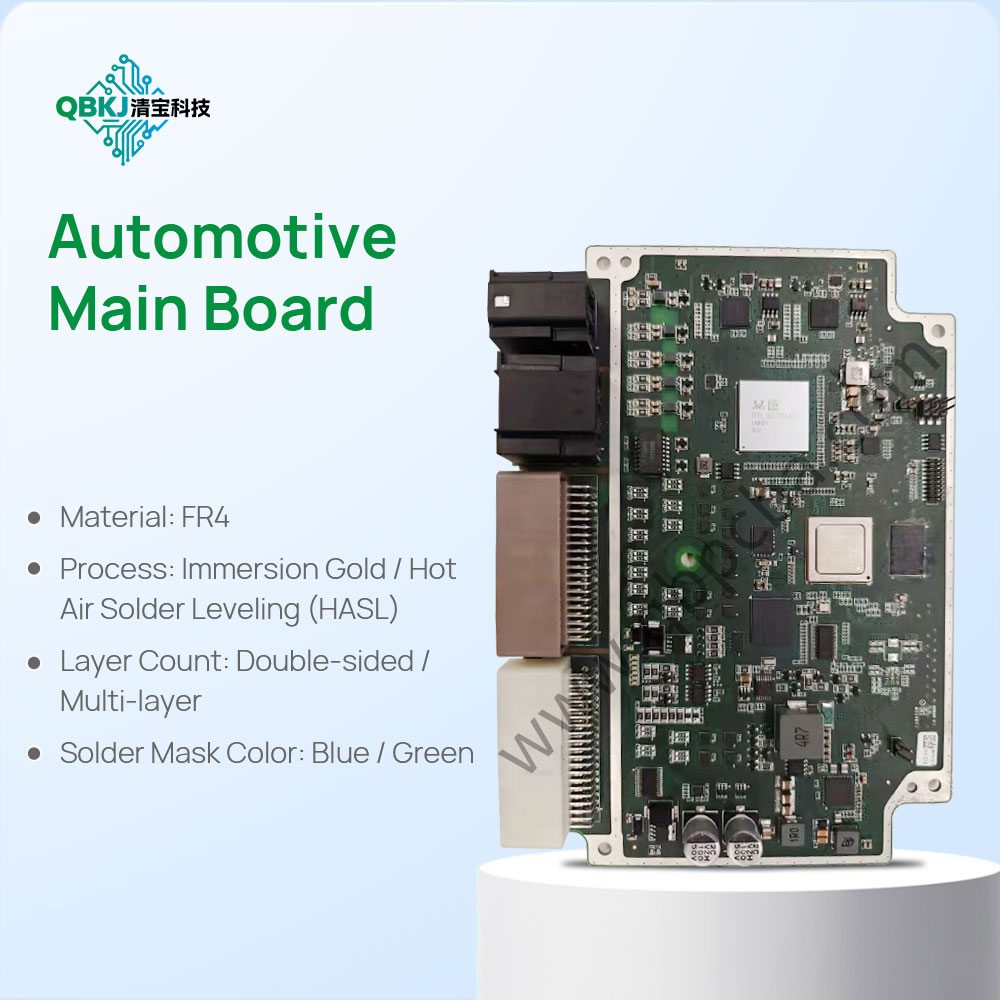
A PCB Copy Assembly Line is a dedicated production line designed to mass-produce copied PCBs (bare boards) by integrating reverse engineering data, automated fabrication equipment, and quality control systems—streamlining the transition from reverse-engineered design to high-volume, consistent PCB copies. Unlike standard PCB assembly lines (using original design files), this line is optimized to handle reversed data and ensure each copied PCB matches the original’s specifications, making it ideal for industries requiring scalable replacement of legacy PCBs (consumer electronics, industrial automation).
The line begins with Design Data Integration: Reverse-engineered Gerber files, drill files, and material specs are loaded into the line’s MES (Manufacturing Execution System), which coordinates all equipment. The MES cross-references data with the original PCB’s “digital twin” (3D scan + electrical specs) to set equipment parameters (e.g., etching time, drill speed).
Next is Automated Material Handling: Substrates (matched to original material) are loaded onto conveyors, which transport them to each station. Copper sheets, solder mask, and surface finish materials are stored in climate-controlled bins to maintain quality, with barcode tracking ensuring material traceability.
Core fabrication stations include: Cutting Station (CNC routers cut substrates to original dimensions), Lamination Station (automated presses bond copper sheets to substrates with precise pressure/temperature), Imaging Station (UV printers transfer reversed trace patterns onto copper, using the digital twin for alignment), Etching Station (automated chemical baths remove excess copper, with real-time monitoring of etch depth), Drilling Station (CNC drills create vias/mounting holes per reversed drill files, with X-ray verification of hole position), Plating Station (electroplating lines coat holes with copper, ensuring conductivity matches the original), and Finishing Station (automated systems apply surface finish—ENIG/HASL—with thickness sensors confirming compliance).
Quality control is integrated at every step: In-Line AOI (after imaging/etching) checks for trace defects, X-ray Scanners (after drilling/plating) verify via integrity, and Electrical Test Stations (end of line) perform continuity and impedance testing—comparing results to the original PCB’s specs. Failed PCBs are automatically diverted for rework or disposal.
The line ends with Packaging & Traceability: Copied PCBs are packaged in anti-static materials, with each unit labeled with a unique ID linked to its fabrication data (material batches, test results). The MES generates a production report for each run, documenting compliance with original specs. Challenges include calibrating equipment to match obsolete manufacturing processes (e.g., older etching chemistry) and scaling for small-batch runs (common with legacy PCBs). This line ensures efficient, consistent mass production of PCB copies.
Email: 1330695973@qq.com
Factory: Room 703, Kelunte R&D Building, No. 1 Ganli 5th Road, Jihua Street, Longgang District, Shenzhen City