CN
-
Service Hotline
15766086363


Release Date:Mar 05, 2026
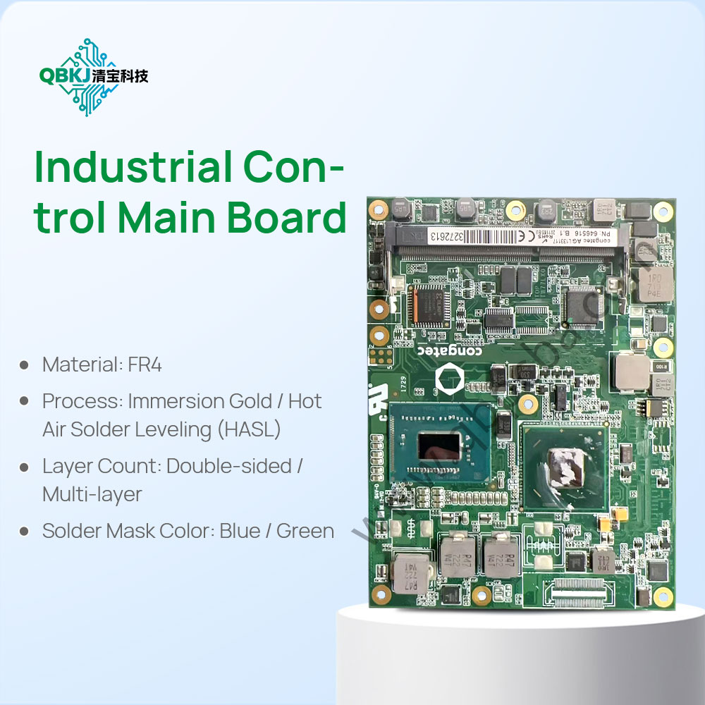
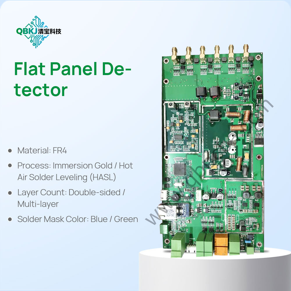
PCB Component Analysis is the process of examining the component footprints, pad designs, and material compatibility of a bare Printed Circuit Board (PCB) to evaluate its ability to support intended components, ensure manufacturing feasibility, and troubleshoot assembly-related issues. Unlike PCBA component analysis (which focuses on populated parts), this process centers on the unpopulated board’s physical and electrical readiness for component mounting—critical for validating PCB designs, optimizing assembly processes, or adapting legacy PCBs for new components.
The workflow starts with Footprint Identification: Using high-magnification tools (e.g., digital microscopes) and PCB design software (e.g., Altium, KiCad), technicians identify each component footprint’s package type (e.g., 0201 SMD, DIP-8, BGA-144) by measuring pad size, spacing, and arrangement. Footprints are cross-referenced with industry standards (e.g., IPC-7351) to confirm compliance with component manufacturer specifications—ensuring, for example, that a QFP footprint’s lead pitch matches the IC’s lead spacing.
Next is Pad Quality & Material Analysis: Pad surface finish (e.g., HASL, ENIG, OSP) is inspected to assess solderability and corrosion resistance—critical for preventing cold joints or solder balling during assembly. Pad integrity is checked for defects like peeling, oxidation, or uneven copper plating using visual inspection or X-ray imaging. Additionally, the PCB’s substrate material (e.g., FR-4, Rogers) is analyzed to confirm it can withstand the thermal stress of component soldering (e.g., reflow oven temperatures) and meet the component’s operating temperature range.
Then comes Electrical Compatibility Testing: Using a multimeter or impedance analyzer, technicians measure pad-to-pad resistance and trace impedance to ensure they align with the component’s electrical requirements—for example, verifying that a high-speed USB trace’s impedance matches the USB standard (90Ω ±10%). Via connections to pads are tested for continuity to avoid open circuits.
Finally, Feasibility Assessment: The analysis results are compiled to evaluate if the PCB can support the intended components. For legacy PCBs, this may involve identifying footprint modifications needed for newer components (e.g., adapting a through-hole resistor footprint to SMD). Challenges include analyzing obsolete footprints with no standard references and verifying compatibility for custom components. This process is essential for reducing assembly defects, ensuring component reliability, and optimizing PCB manufacturing workflows.
Email: 1330695973@qq.com
Factory: Room 703, Kelunte R&D Building, No. 1 Ganli 5th Road, Jihua Street, Longgang District, Shenzhen City