CN
-
Service Hotline
15766086363


Release Date:Jan 26, 2026
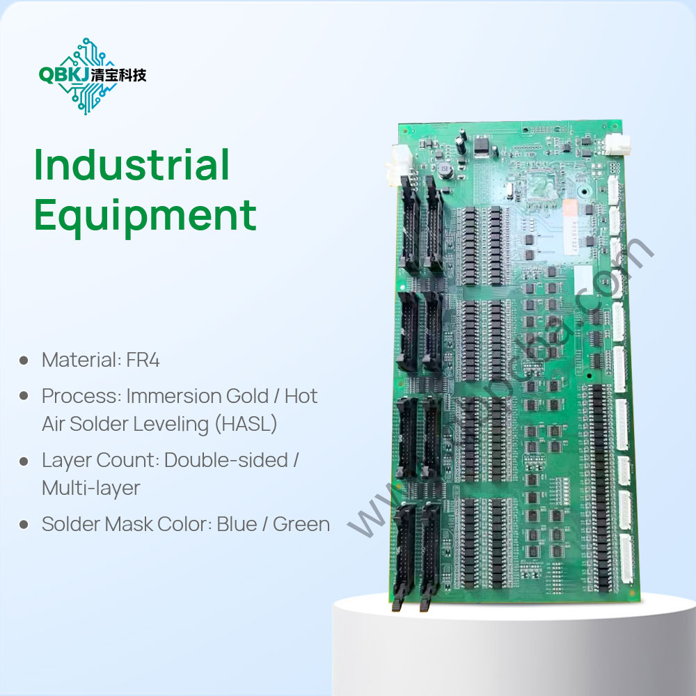
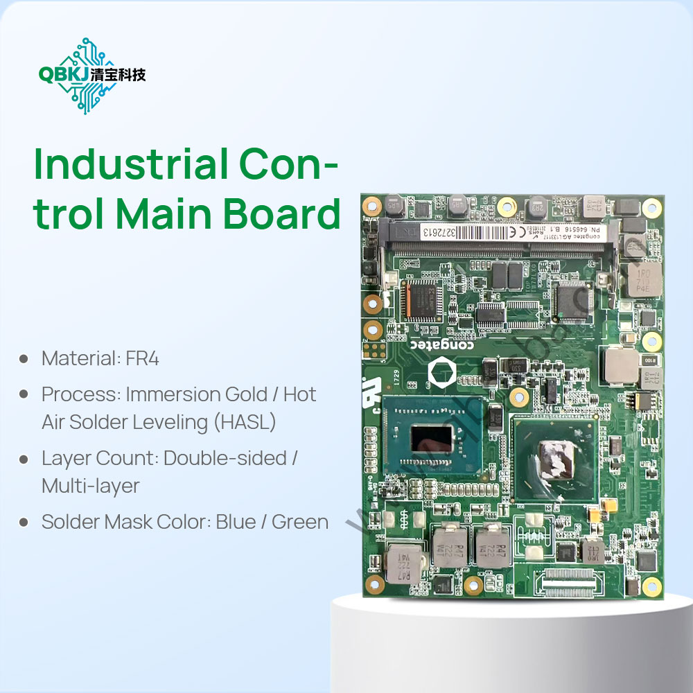
Reverse PCBA Production refers to the end-to-end process of recreating a fully functional Printed Circuit Board Assembly (PCBA) by first extracting design and component data from an existing physical PCBA, then replicating its manufacturing workflow. Unlike traditional PCBA production (which starts with original schematics and BOMs), this process begins with meticulous teardown: technicians use anti-static tools (e.g., precision desoldering irons, ESD-safe tweezers) to remove components, documenting each part’s part number, manufacturer, orientation, and solder pad details.
After teardown, PCB reverse engineering is conducted to map trace routes, layer stackups, and via positions, generating editable Gerber files and schematics. Component validation follows—each part is tested (via multimeters, oscilloscopes, or component testers) to confirm functionality and ensure compatibility with modern equivalents (critical for obsolete parts). The production phase then mirrors standard PCBA manufacturing: PCB fabrication using reversed Gerber files, component sourcing (prioritizing original or qualified alternates), automated SMT assembly (for miniaturized parts like 0201 resistors), and through-hole soldering for larger components.
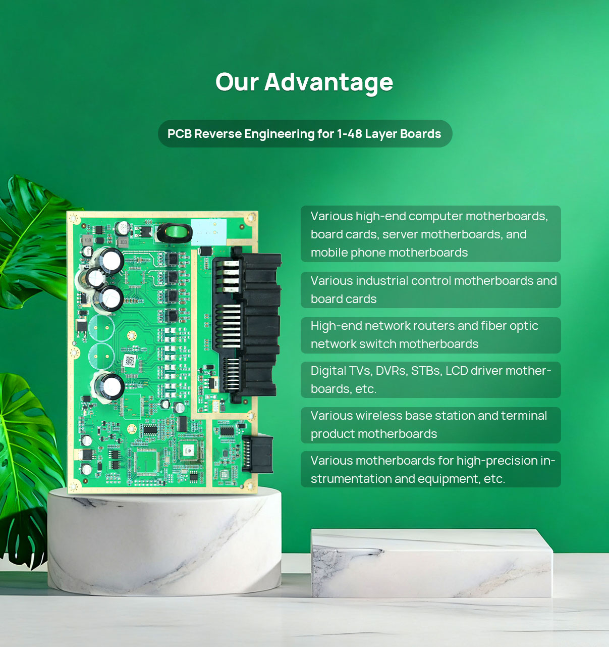
Post-production, rigorous testing (e.g., in-circuit testing, functional testing, X-ray inspection for BGA solder joints) ensures the reversed PCBA matches the original’s performance, including power consumption, signal integrity, and environmental resilience. This process is vital for replacing legacy PCBAs (e.g., in industrial machinery or medical devices where original designs are lost) and scaling low-volume repairs. Challenges include sourcing rare components and maintaining solder joint quality to avoid reliability issues, requiring collaboration with specialized component distributors and certified manufacturers.
Email: 1330695973@qq.com
Factory: Room 703, Kelunte R&D Building, No. 1 Ganli 5th Road, Jihua Street, Longgang District, Shenzhen City