CN
-
Service Hotline
15766086363


Release Date:Dec 26, 2025
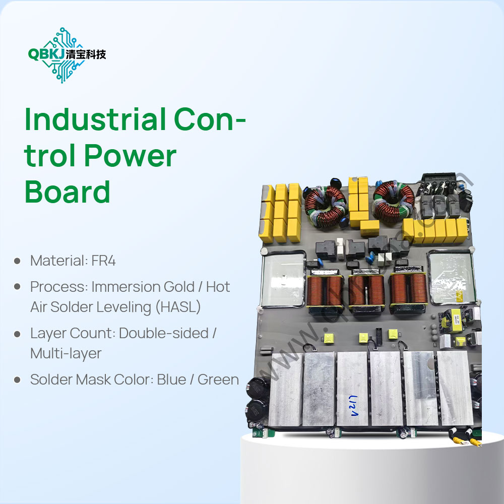
PCBA clone modification refers to the process of adjusting or enhancing a cloned Printed Circuit Board Assembly (PCBA) to meet specific functional, performance, or design requirements that differ from the original. This process begins with a thorough analysis of the original PCBA’s schematic, bill of materials (BOM), and layout to identify areas for modification. Engineers may need to replace certain components—for example, upgrading a low-power microcontroller to a higher-performance model to support additional features, or swapping standard capacitors with high-temperature variants for industrial applications.
Key steps include schematic redesign, where changes are made to circuit paths or component connections using CAD software, followed by PCB layout adjustment to ensure modified components fit physically and maintain proper signal integrity. Thermal management is often a critical consideration during modification; adding heat sinks or adjusting trace widths may be necessary if new components generate more heat. Additionally, compatibility with existing systems or new interfaces (such as USB-C instead of USB-A) may drive modifications. Rigorous testing after modification is essential to verify that the adjusted PCBA functions correctly, meets safety standards, and avoids unintended side effects like signal interference or component failure. This process not only adapts cloned PCBs to unique use cases but also helps businesses optimize costs by leveraging existing designs while tailoring them to specific market needs.
Email: 1330695973@qq.com
Factory: Room 703, Kelunte R&D Building, No. 1 Ganli 5th Road, Jihua Street, Longgang District, Shenzhen City