CN
-
Service Hotline
15766086363


Release Date:Mar 07, 2026
Reverse Engineering for Quality Test uses extracted design data from physical products or components to develop robust testing protocols, validate manufacturing consistency, or root-cause quality issues—ensuring that products meet predefined standards, perform reliably, and comply with regulations. Unlike standard quality testing (which relies on original design specs), this process fills gaps when documentation is lost, incomplete, or outdated, making it critical for legacy product maintenance, third-party quality audits, and supplier verification.
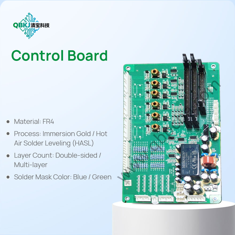
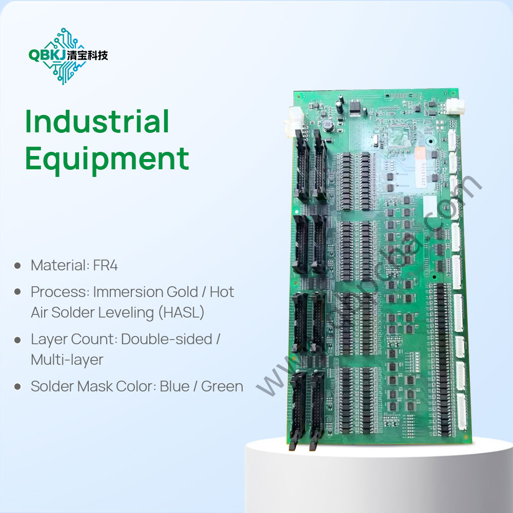
The workflow begins with Test Goal Alignment: Teams define quality objectives—e.g., verifying that a batch of PCBs meets trace impedance standards, identifying why a component fails under thermal stress, or confirming that a supplier’s product matches the original design. Next is Design Data Extraction: The product is reverse-engineered to capture critical quality-related details—such as PCB trace widths (for current-carrying capacity), component tolerance ranges (e.g., a resistor’s ±5% value), mechanical dimensional tolerances (e.g., enclosure fit), and software performance benchmarks (e.g., firmware response time).
Using this data, Test Protocol Development follows: Engineers create customized tests to validate each quality parameter—for example, using an impedance analyzer to check if PCB traces meet the reversed design’s 90Ω ±10% standard, or using a thermal chamber to simulate stress conditions and measure component performance against reversed thermal specs. For complex systems like PCBAs, this may include in-circuit testing (to verify component connections) and functional testing (to ensure the product operates as intended).
Then comes Test Execution & Analysis: The protocols are run on samples (e.g., a batch of PCBs, a supplier’s components), with results compared to reversed design data. Any deviations—such as a trace impedance of 105Ω (exceeding the 90Ω ±10% limit) or a component’s capacitance outside the labeled range—are analyzed to identify root causes (e.g., manufacturing defects, counterfeit parts).
Finally, Reporting & Corrective Action: A detailed quality report is delivered, highlighting non-conformities, their impacts (e.g., reduced signal integrity), and recommended fixes (e.g., adjusting PCB etching parameters, sourcing components from authorized distributors). For ongoing quality control, consultancies may also help clients integrate reversed design data into their manufacturing test systems (e.g., AOI machines). Challenges include developing tests for highly integrated components (e.g., system-on-chips with no external test points) and ensuring test protocols account for normal wear and tear (vs. manufacturing defects). This process is essential for maintaining product reliability, reducing warranty claims, and ensuring compliance with industry standards like ISO 9001 (quality management) and IPC-A-600 (PCB quality).
Email: 1330695973@qq.com
Factory: Room 703, Kelunte R&D Building, No. 1 Ganli 5th Road, Jihua Street, Longgang District, Shenzhen City